For help with anything related to operating the scanner: including using the scanner console, transferring data, and MR safety and training? Contact Larry White (lawrence_white@fas.harvard.edu).
Getting Started
What equipment is available?
For detailed information about the equipment available in the CBS, see the Infrastructure and Equipment page. In addition, there is a resource description located on the Policies page under External Funding, that can be included in grant applications.
For papers, the projector we use is a InFocus IN5542.
How do I join the mailing list? When is the next safety class?
Everyone using the MRI facility should be on the CBSN users mailing list, as this is the forum for announcing important information regarding the scanner. Any user can also use it to announce scan time for trade, or any other information generally of interest to the scanning community.
It is also where upcoming safety classes are announced.
What are the general polices and procedures of the scanning facility?
The documentation around MR safety procedures can be found here, including training, safety screening (and the participant screening form), emergency procedures, and MRI suite rules
The documentation around administrative policies can be found here, including scheduling, billing, IRB, and funding.
How do I schedule time for rooms and/or equipment?
The CBSN calendar can be found here. This includes calendars to schedule time with the scanner, mock scanner, TMS, physiology testing room, and behavioral testing room.
In addition, the Administrative Policies page includes information about requesting scan time in general – including how to request recurring time blocks – and scan time costs.
Running a Scan
How do I register a subject on the scanner?
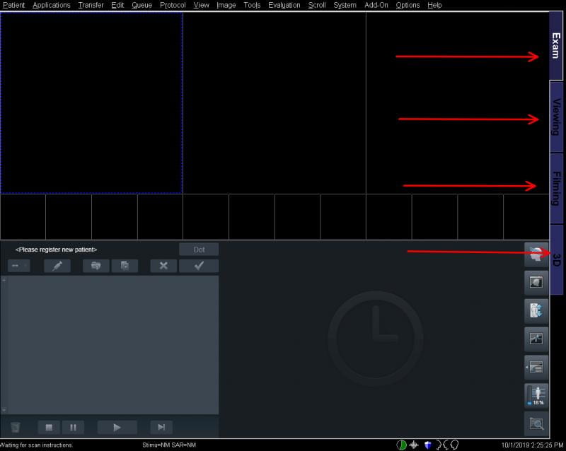
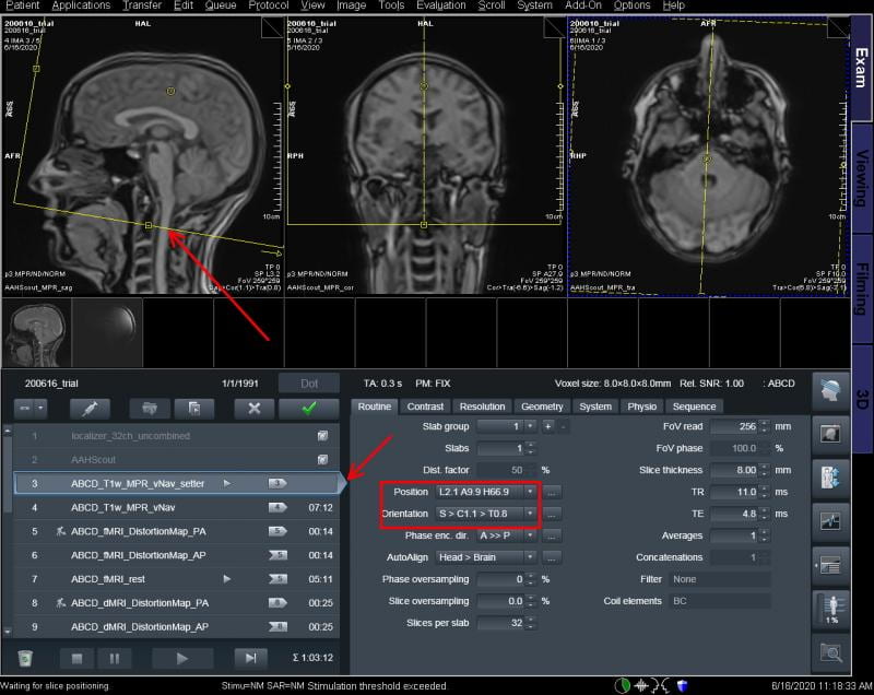
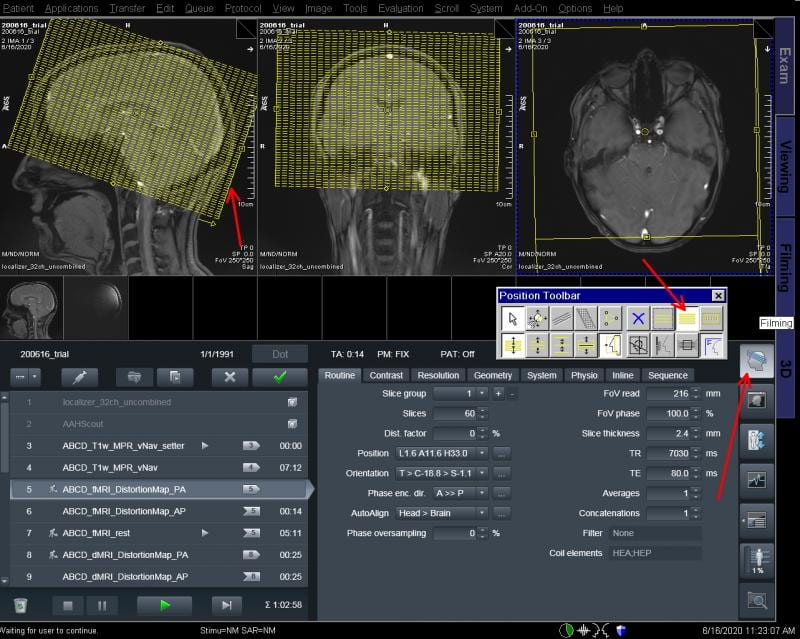
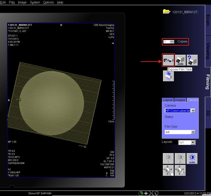
There are four task cards along the right hand side of the screen: EXAM, VIEWING, FILMING, and 3D (red arrows, below).
- EXAM is the interface that allows us to acquire data.
- VIEWING is where you can look at images that have been previously collected.
- FILMING is where you can prepare images to be printed (see below).
- 3D allows you to view 3D datasets (Structural MPRAGE) in all three orientations.
You want to select the EXAM card to start your study.
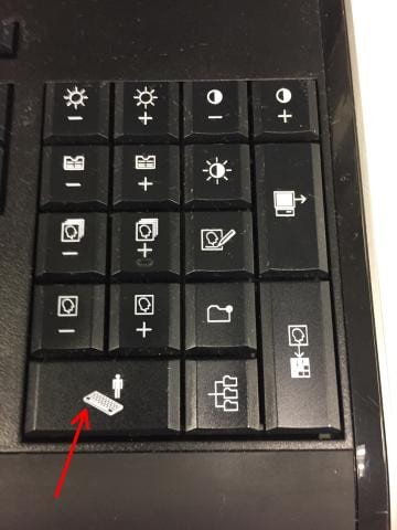
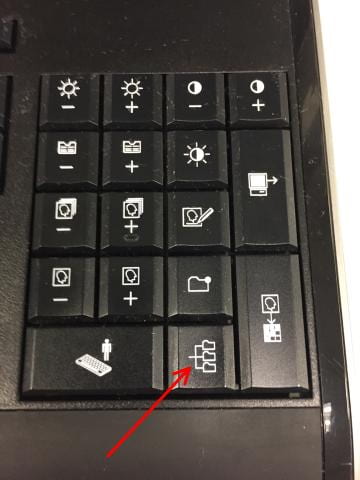
Next, in the Patient pull down menu (top left corner) select Registration. Alternatively, press the key on the keyboard (right hand corner) that has a small person and a keyboard (below):
Pressing this will bring up the registration panel. You need to fill in all the boxes that have bold writing (red arrows, below). You will not have an option to click EXAM until all these are filled out. Remember never use patient identifiers as this is a violation of the Health Insurance Portability and Accountability Act (HIPAA):
- Last name: The proper naming convention is
YearMoDay_XXXX, whereXis individual lab’s preferred coding convention. (e.g.,220101_studyName_sub01for January 1st, 2022). - Patient ID: Copy and paste Last name field here
- Date of birth should be listed with the date and month as 1, and the actual subject’s year of birth (example: 1/1/1990).
- Sex: Don’t forget this one!
- Height/Weight: Enter the subject’s weight in pounds and height in feet/inches. If this information is given in metric, click the “Metric” check box and the information can be entered in metric units.
- Additional info: We require the CBS Central project ID to be entered in the Additional Info field.
- To specify the project, enter:
Project:<ProjectID> - Note there is no space before or after the colon, and nothing after the project ID. eg:
Project:Buckner - If you know the subject name/code you plan to use on CBS Central, you can enter:
Project:<ProjectID>,Subject:<SubjectID> AA:True
where there is no space before or after the colons or comma, only one space beforeAA. AA:Trueensures the session is auto-archived on CBS Central. eg:Project:scantest,Subject:ADNI_phantom AA:True
- To specify the project, enter:
- Patient position: Press the arrow and select the first option: Head First – Supine.
- This is very important. If you accidentally select the second one, your slices will be reversed, instead of going from the bottom to the top of the head they will go top to bottom. Watch out for this as it is easy to do. (The easiest way to correct this if it happens is to reregister the person and start over.)
- Operator: Enter the initials (or last names) of all users present with green badges
NOTE: You can semi-automate much of this registration process if the previous scan from your study is still on the scanner database (in the Patient Browser). Most of the registration fields can be pre-populated, which avoids having to constantly type (and risk a typo) lengthy session name formats, and the Project ID information. To do this, make sure the previous session in your study is highlighted in the patient browser, and then press the keyboard button for patient registration.
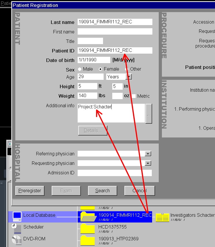
This results in the subject/session/demographic AND Additional Info from the previous session to be automatically populated in the Registration panel. Now, you only need to modify the demographic info for the new subject, and edit the session name for the new session. In this example, just edit 220914_FIMMRI113_REC to, eg: 220918_FIMMRI113_REC, and update the age/sex/weight/height for the new subject. This avoids a lot of painful typing and typo-ing of session names and Project info. This is even more useful when the same subject is being registered for multiple sessions, as you don’t have to re-enter their demographic information each time.
Once all this has been entered, click Exam to move to the registration confirmation page.
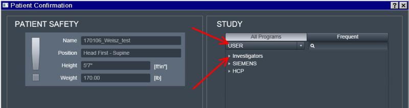
To choose your study protocol folder, ensure the USER tree is active in the top center of the Confirmation panel, and then under that, ensure the Investigators tree is open (or click Investigators to open it). The full list of investigators and their study folders should now display:
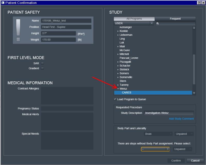
In the INVESTIGATORS list, select your name or the name of the PI (eg. Weisz) and then the name of the Study under the PI’s name (eg. CARES).
Under the list of investigators is a check-box for “Load Program to Queue” This is checked by default, however if you don’t want the entire study folder to go in the scan queue, you can uncheck it now. If the Body Part box at the bottom is circled in orange, choose Brain. At this point, the Confirm button becomes active, and you can press confirm.
How do I conduct a typical scan?
See here for a summary of our default protocol.
Loading sequences
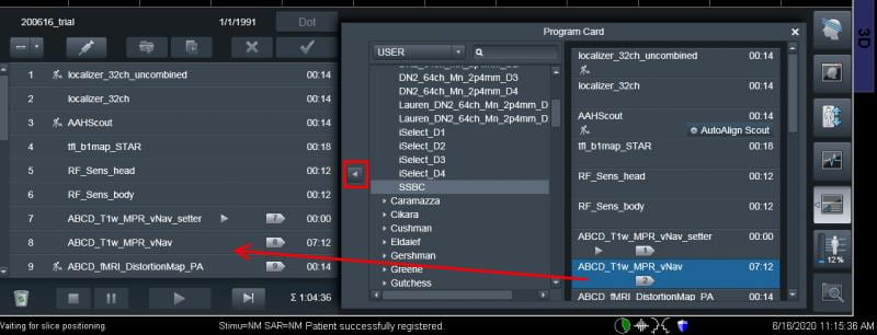
On the lower right half of the screen all of the sequences within the protocol you selected during registration will appear. If you had “Load Program to Queue” checked on the second page of registration (above), they will also appear in the scan queue on the bottom left of the screen. However, if that was not the case, or you want extra scans included, you must move them over to the lower left by dragging them over (shown below, red arrow), or highlighting the sequences you want and clicking the (<) button (red box below).
Localizer
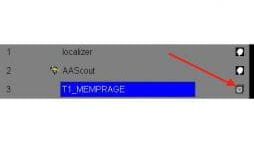
The first sequence is always a localizer. If you look on the right of the localizer sequence you will notice that the localizer does not have the small “working person” icon beside it (pictured below in the red box), as some other sequences below it do (e.g., scan #3 shown below). The lack of this icon means that as soon as the localizer is moved to the left side it will automatically run. Make sure you let your subject know! All of the parameters have been pre-programmed. The green circle (red box below) will slowly fill to show the progress of the scan.
As soon as the localizer is complete, the single-slice sagittal, coronal and axial views will fill the viewing windows at the top of the screen. Because the next scan has a “working man” icon, that scan’s parameters will open for inspection – this is also indicated by the gray arrow from the scan name in the queue, pointing at the parameter window. The scan will not run until you press the green check mark. Before doing so, you should check the brain is roughly centered in the FOV in the graphics segments at the top of the screen.
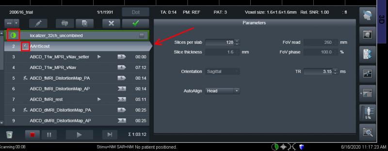
AutoAlign (AAScout)
Second is sequence is usually the Autoalign, which allows the slice placement of subsequent scans to automatically align (For BOLD scans, the default slice angle is tilted steeper than the AC/PC Line). In the figure above, AutoAlign is about to run. When Autoalign is acquired successfully it puts new 3-axis images in the graphics segments, and updates the field-of-view position based on the subject’s head position.
You may note the yellow boxes , which indicate the field-of-view for the next scan, have moved – and position parameters have changed (figure below). If you have not yet put the MPRAGE or any other protocols in the scan queue, when you move the next sequence to the scan queue and open it, (by double click, or right click and selecting Open), it will open with the field of view properly positioned on the brain based on the AAScout results (i.e., tilts slice box to compensate for the participant’s positioning).
However, if you choose to not use the Autoalign, or don’t like the way it aligned your slices, you are responsible for positioning the slice prescription for the rest of the protocol. Also, please note that Autoalign uses the body-coil, so if you happen to notice this, don’t worry, it is correct.
Structural Scan
If it’s not already there, the structural scan (T1 MPRAGE or MEMPRAGE) should be brought to the left panel and opened as described above.
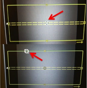
Once opened, the sequence parameters will be in the lower right side panel. The parameters are displayed on many tabs but always open on the Routine Card (Fig. 3, above). Check the position of the yellow field-of-view/slice box. The example above shows where a 3D navigator will be acquired to track motion throughout the MPRAGE scan – the yellow box position for the MPRAGE scan itself will be somewhat lower. Anatomy cut off (such as the nose) can wrap and end up in the occipital lobe, so make sure you try and capture the nose within the box.
To move the volume, left click the center dot (in the middle of the yellow box, with the double lines going through it). To rotate the volume, move the cursor over the centerline until you see a circular double arrow, hold the left mouse button down and rotate as needed. Grabbing any of the sides can change the FOV or slice thickness (not something you usually want to do).
Tell the subject that the sequence is going to begin and click the big green check mark to start the scan.
Check the Structural Scan
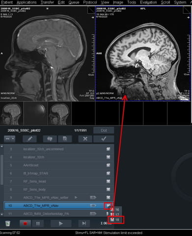
Wait for the MPRAGE reconstruction to finish. This may take a few seconds, especially if the 32-channel coil is used, and if its a multi-echo MPRAGE. When the head icon is hollow (figure below, red arrow), the reconstruction is still going on. When the reconstruction has completed, a head profile icon will now be solid (figure below, upper two heads). Click on this icon.
If only one series is present, drag the icon with the left mouse into one of the three window segments (figure below). If more than one series is present under the head profile icon – as will happen if you ran a multi-echo MPRAGE or reconstruct the scan without and with intensity normalization, click on and drag only the highest series number – this is the summed average result of the multi-echo MPRAGE acquisition, or the intensity-normalized version of the scan (red arrow, figure below). Please note that the center slice of this series will appear in the window.
Use the dog-ears in the right upper corner to go forward and back in the image series until you find the region you want to view the positioning of your BOLD your slices on. Also, go through the entire series to check for motion.
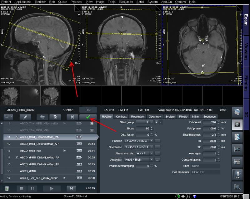
Field Maps & EPI Scan
If you’ve acquiring spin-echo field map scans, do this and then the EPI run; all the slice-placement information applies to both the field-map scans and the BOLD itself. If AAScout was used, open the sequence and make sure the automatically centered slices are positioned correctly, then click the green check box to run the scan. Please note that on occasion AutoAlign may not position the slices as you desire them, therefore you will need to manually set your slice prescription, as described below. The below figure shows the slice box for the EPI positioned on the initial three-axis localizer image, but if you’ve dragged the MPRAGE image up there, you can scroll through the 3D MPRAGE scan to see where the slice box will lie in every slice of the MPRAGE.
The actual position of the individual slices can be visualized by toggling the slice view buttons in the slice position toolbar shown at right below. This is found by clicking on the head icon with the blue slice marks (red arrow at right, figure below) and then toggling the slice display buttons in the top right of the slice position toolbar. Don’t use the buttons on the left of the toolbar – you could change your slice thickness or spacing! The individual slices are shown overlaid on the brain in yellow below.
Testing a Field Map or BOLD protocol
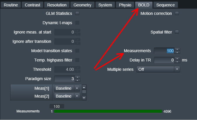
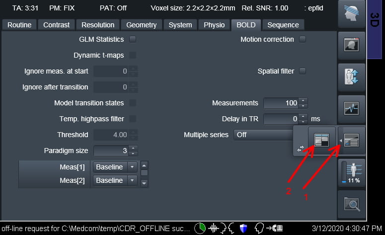
The working person icon indicates the spin-echo field map (or BOLD) protocol is open for editing. To ensure you are capturing everything that you want, it is recommended that you run a test EPI functional run with 2-4 measurements (time points) to ensure the slice positioning and quality are good. You can use your regular fMRI sequence and just change the number of time points manually. This can be changed on the BOLD Card (below, arrow), in the field Measurements. Enter 2 and then hit return. This should be done before you run any other optional scans such as the field map or T1w EPI scan. Importantly, you will have to copy the slice placement information to scans coming afterwards, as described next.
If AutoAlign was used and you didn’t move the slices, then you can now hit the green check mark to run the field maps scans and the BOLD scans. However, if you changed the slice box, you need to copy the slice information from the test EPI. To achieve this:
- Open the sequence.
- Right-click the 2-measurement functional run with the proper slice positioning.
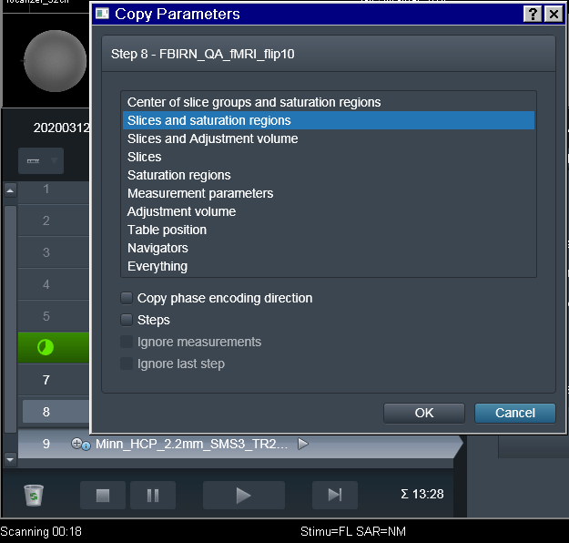
- Select Copy parameters from the menu.
- From the list of parameters you want the second option, Slices & saturation regions.
For more complete instructions on repositioning the slices on later sequences, see here. Now the new sequence slices are in the same location as the 2-measurement functional run. Hit Apply when positioned properly.
Running the Field Map / BOLD Scan
Now you’re ready for the BOLD scan. The acquisition time of the scan will be indicated at the upper left corner of the parameter window. Remember that the time includes any dummy scans so; deduct number-of-dummies x TR from the time of the scan to calculate the length of your paradigm. Please note, if you are using iPAT or SMS, there will be additional time added on also, however the first trigger will always come with the first ‘real’ scan.
Click the green check mark.
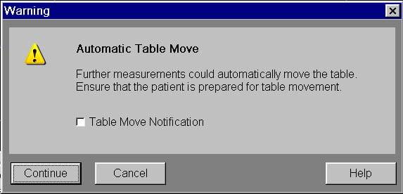
The EPI scans always have a two-step process to begin. Clicking green check mark begins the pre-scan routine of frequency and shim check. All other scans begin automatically at this point, however for a BOLD scan, you may want to not start the scan until your subject and stimulus computer are ready. The “gray triangle” icon beside the scan name (red box, below) achieves this: instead of the scan starting automatically, a pop up window will appear.
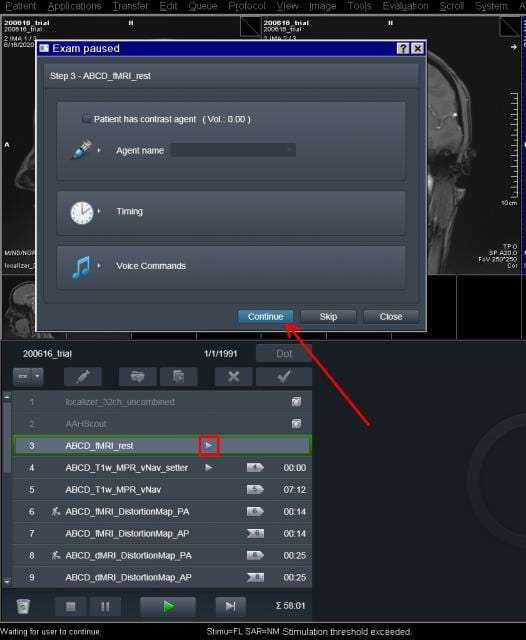
When you have everything ready to go, click Continue (red arrow above). The scan begins immediately. If you want more runs with the exact same parameters, right click on the one you want to copy and select append. If you want the same slice prescription but a different # of measurements, right click on the functional, select append, open, and make the changes as described above and click the green check box.
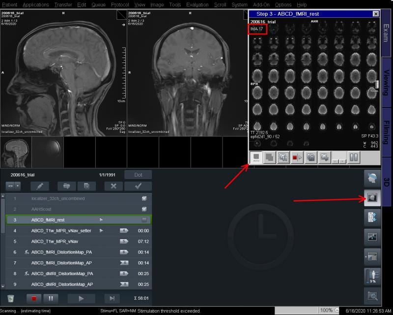
Make sure to open the Inline Display (figure below, top right box), if it doesn’t open automatically. You open it by clicking the head icon at far right, and can expand it by dragging the corner. Inline Display shows your functional images immediately after the images are reconstructed – image number is given in the upper left of this window. This allows you to monitor if your subject is moving, or if there are unwanted artifacts.
How do I move my slices (after AutoAlign fails)?
To move your slices, hover the cursor over the center of the yellow FOV box. The cursor will change to a cross shape (top, image below), meaning it is safe to drag the box around. If you want to rotate your slices, move your cursor to the edge of the box till you get a double arrow circle icon (bottom, image below), then you can drag and rotate. If you drag or grab anywhere else, you could change the FOV, which is bad and can change things like your voxel size.
Once you verify that this is where you want your slices, usually via a test a couple of timepoints, you will have to copy the slice information to future scans that should use the same FOV, such as other BOLDs, T1w EPI, or fieldmap. To do this:
- Bring over your next scan from the protocol list at the right.
- Double click it to open it (lighter gray and and an arrow to the parameter table at right).
- Then right click the test EPI or functional run with the proper slice positioning and select Copy parameters from the menu.
- From the list of parameters you want the second option, Slices & saturation regions
- Click OK. Now the slices for the new scan are in the same location as the test functional run.
- You can hit the green check mark to use the updated slices and run the scan.
This has to be done for every new BOLD run you bring over from the protocol browser on the right. Alternatively, if you are running a bunch of the same BOLDs in a row, you can right click on the current one and hit append, this will place another copy of the run in the list, and will include the updated slice information.
Why does the scanner tell me the patient bed might move when I start the first scan?
Until a reference scan has been acquired, the scanner is using as its frame of reference the magnet isocenter – the center of the magnetic field, which is in the geometric center of the bore tube. This could, in principle, differ from the reference position, called REFERENCE, which we use. The reference we want to use is the center of our subject’s head, which we have just marked with the laser prior to putting the bed into the magnet.
As soon as a localizer (or any other image) has been acquired using the REFERENCE positioning mode, the scanner software then ‘knows’ to reference all subsequent images relative to that first image. This allows you to prescribe slices on each subsequent image however you like, and the scanner will track where you are in space. This stays true throughout your scan session provided you don’t move the patient table.
How long will my scan take? Where is the scan time shown?
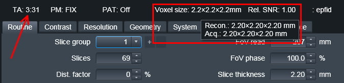
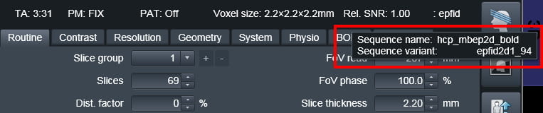
On the Exam display, look approximately halfway down the screen, below the three image display windows and immediately above the parameter card area. In a white color is a line of information, for example:
The time of the scan can be found under:
- TA = time of acquisition: 3 mins 31 seconds. This includes time for dummy scans and any additional reference scans needed if using iPAT or SMS.
Other information about your scan is also displayed:
- PM = positioning mode: FIX indicates fixed positioning mode, meaning the slice position is set by the positioning parameters below (although AAScout may have adjusted them for your subject).
- PAT Off: indicates iPAT (parallel imaging) is not in use for this scan. (When parallel imaging is turned on with an acceleration factor of 2, this reads PAT: 2)
- Voxel size: is 2.2 x 2.2 x 2.2 mm. To get voxel size with two decimal place precision, place the mouse over the Voxel size field. It pops up in a new text box, as shown above.
- Relative SNR: you can ignore. It will always appear as 1 unless you change acquisition parameters.
- epfid: The abbreviated pulse sequence family being used is labeled as epfid. This applies to any EPI-BOLD scan, so is not helpful. Place the cursor over the epfid word and a popup (below) will tell you which exact pulse sequence (binary file) is in use – in this case, “hcp_mbep2d_bold”.
Transferring Data and Protocols
How do I send my data to CBSCentral?
- Open the data browser through the patient pull down menu or by hitting the button in the lower right hand corner that has a folder tree file on it.
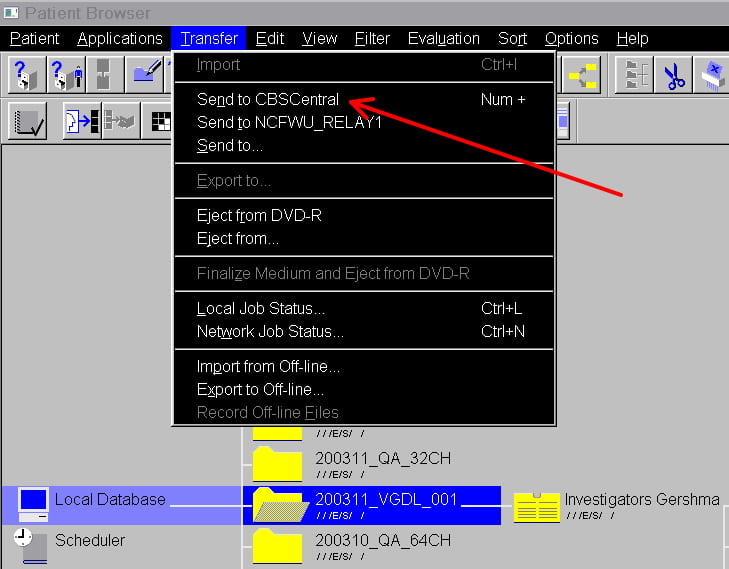
- Highlight your subject or session, but ensure a specific series/scan is not highlighted (otherwise only the highlighted scan will be sent).
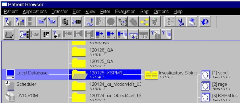
- Under the Transfer menu, select select “Send to CBSCentral“. Your study will now go to the server.
- Once there, you need to manually archive it (unless you set the session up to auto-archive when you registered the subject). Otherwise you will not be able to access the data for analysis)
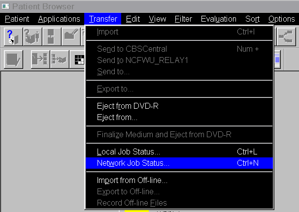
- Go back to the Transfer menu at the top of the screen and select Network Job Status (see below) to make sure the DICOM transfer is working. Make sure your transfer moves from Spooling to Active and that it is transferring Entire Patient and not just a volume or subset of volumes.
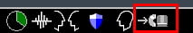
- You can also look for the network-send icon at the bottom of the screen (below).

How do I export my data to an external drive?
Please Note: USB Drives may only be plugged into the satellite console. They should never be plugged into the main host PC. Follow these steps only on the satellite console!! This protects the host PC from picking up viruses and malware.
To maintain your own personal back-ups of your data, we highly recommend the use of a portable USB hard-drive. These are the fastest way to export your data after the network send. In a pinch, a FLASH drive can be used, but these are usually slower, and not recommended for long-term storage. Make sure what ever storage device choose to use does not want to install any software on the satellite console because you will not be allowed to and then the console computer may not be able to mount the drive.
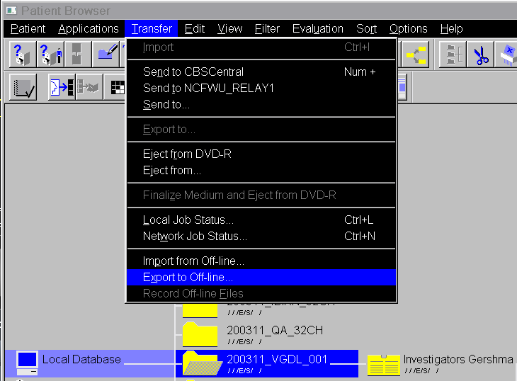
- Ensure your USB drive is plugged into one of the USB ports on the front of the satellite console computer.Highlight your study in the subject/data browser. As shown for sending to CBSCentral, highlight your subject or session, but ensure a specific series/scan is not highlighted. Then, use the transfer pull down menu and choose “Export to Offline”.
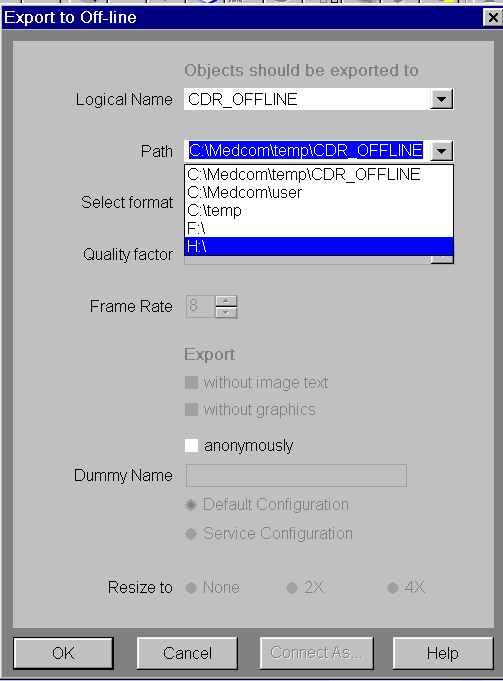
- A second window will now appear. Choose the destination for your exported files. Do not choose a location on the C: drive – this space is needed for the Siemens system to operate smoothly and data found here will be deleted. USB portable hard-drives and FLASH drives plugged in to the USB port on the front of the satellite console computer usually appear as drive H: or J:. Choose the drive where your USB external drive is located, and then click “OK”
- Go back to the transfer menu and select local job status (right above network status, as shown for sending to CBSCentral) to make sure the file export is working. You can also look for the data-export icon at the bottom of the screen (below).
How do I print the slice prescription?
There are two options for this. One is a general method for printing things you want from the scanner and involves grabbing the entire screen. The second way is more specific to printing the slices and uses the print tools within the scanner software.
Printing via Print Screen:
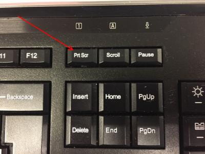
- Hit the PrtScr button at the top of the keyboard, above the cursor keys. A copy of the entire screen is saved on the clipboard in Windows 7.
- Press Control and Escape (on the keyboard) at the same time.
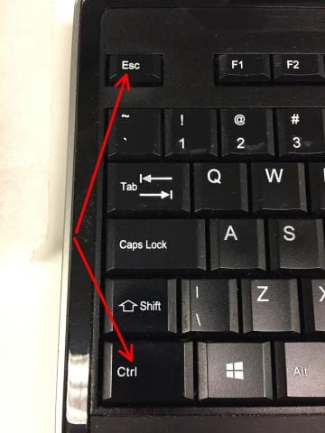
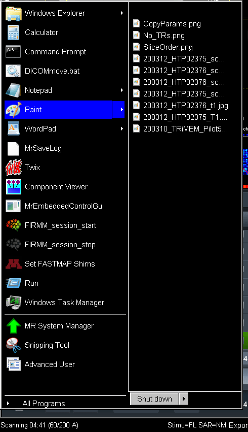
- This brings up the Windows start-up menu from the bottom left of the screen. Move the Cursor up and choose Paint. Paint is a crude image processing application in Windows (like Notepad is to MS Word) You’ll get a blank canvas.
- Use Ctl-V or pull down edit/paste to paste your screenshot into Paint.
- You can trim the screenshot down to just the desired portion of the screen, if you choose. However, this is done by selecting the sections to delete, so it can become tedious.
- You can print directly to the printer in the computer room adjacent to the scanner room, although if you print the entire screenshot without trimming, it will print on multiple pages.
- You can save the screen-shot to your USB FLASH or external USB hard-drive, in jpg, tiff or png format, for later use such as annotating or for inclusion in documents, etc.
Printing within Syngo
- Make the sagittal with the slice prescription the active window by clicking on it. A blue box will appear around it.
- Hit the button in the lower right hand corner of the keyboard that looks like a sheet of film. This will send the active image to the filming page.
- Go to the FILMING page, a tab on the right of the screen. The image will be in the upper left hand corner of the page.
- Go to the Camera tab and make sure that the setting is for the laser printer, not PDF.
- Select the layouts: 1×1 option..
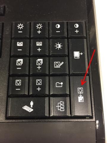
- Click the left icon that looks like a printer with a sheet of film coming out of it (red arrow below), this is the printer. The image will be printed on the printer in the computer cluster room in the basement. If you want multiple copies, change the number of copies.
How do I print my scan protocol?
- Go to the third icon from the bottom on the right hand side of the screen in the exam card.
- On the left side of the icon, there’s a small arrow pointing left. If you click on that (1 below), a second icon pops out to the left. Click on that second icon next (2 below).
- This brings up the Dot Cockpit, or protocol tree, listing all the protocols on the scanner. Find the correct investigator folder on the left (1 below) and then correct protocol folder (2 below).
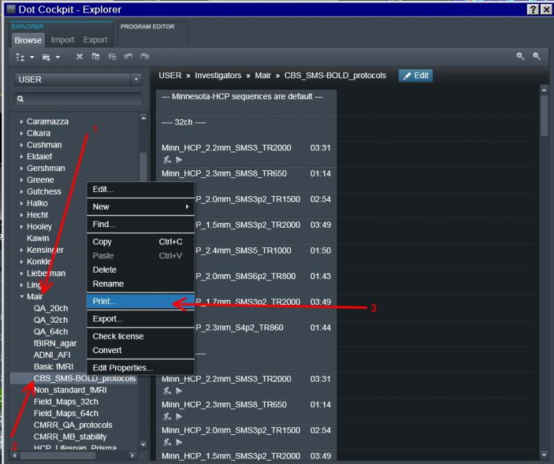
- Either right click on entire protocol if you want every scan or right click on the individual scan you want.
- Choose print or export depending on if you want a pdf printout or a binary file (exar1) that can be imported onto another Siemens scanner (3 above).
- Choose a temporary location to write the file to, and click ok.
- The file can be removed later via a USB drive from the satellite console. A pdf printout can then be printed from another computer if you need to use paper.
Troubleshooting
I can’t hear anything happening! How can I tell what the scanner is doing?
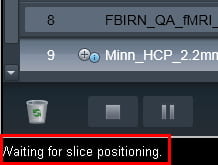
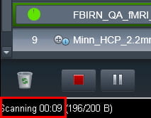
Look in the very bottom left-hand corner of the screen. It might say, for example: “Waiting for scan instructions,” or “Waiting for slice positioning,” or “Scanning 00:09 (196/200 B).” That last message tells you there are 9 seconds left in the current scan, and that it’s just finished acquiring 196 of 200 repetitions in a time series. The other messages are usually self-explanatory.
How do I reset the table?
On rare occasions, the patient table may freezes if something gets caught in its guide-path, or the scanner gets confused. The solution, for the most part, depends on what happened to cause this in the first place. The Prisma system has a very detailed screen above the magnet bore, and the instructions to solve the table issue will be given on this screen. Just follow the instructions for the particular problem at hand.
The scanner doesn’t seem to be working properly, how can I tell what is wrong and what can I do?
All warnings and errors are represented as pop up boxes and/or as icons at the bottom of the screen.
This is what it looks like without any errors:![]()
The green pie chart indicates how full the system’s image storage capacity is. Holding the mouse over the pie chart gives the exact database capacity in a pop-up. We keep this under 70% to ensure smooth operation of the scanner. The waveform indicates the scanner’s acquisition system. When there is a warning about a particular system, there will be a yellow line through it:![]()
When there is an error, there will be a red line:![]()
To view what the error/warning is, click on the icon. A pop up box will have the message. If you choose okay, it will clear the message, so it is generally better to press the close button so that these don’t get cleared. It is also a good idea to write down or take a screen shot of the message so that you can relay it to Ross (rmair@fas.harvard.edu) and Larry (lawrence_white@fas.harvard.edu). This is true for messages that start as a pop up box also. If you have an error/warning during regular business hours you should try and contact Larry or Ross for help on how to solve the problem. Their contact numbers are listed on the white board in the scan room. If it is after hours you can try Larry’s cell phone. If he doesn’t pick up you can leave a message and he will get back to you if she can. However, there is no guarantee; that is the risk that comes from scanning outside of business hours. There should usually be someone around from 9-5:30 during weekdays.
If you can’t get ahold of anyone and feel brave enough (aka experienced enough) to troubleshoot on your own you can try some of the tricks below. After noting the error/warning you can check on the status of that component via the System Manager. To access this, go to System (located in the bar at the top of the screen), and then go to Control via the pull down window.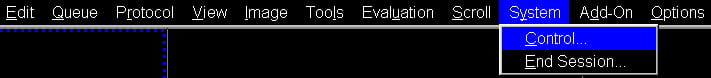
This will bring up a box with four tabs at the top – Host, Meas & Recon, Periphery, and Tools (see below). You can check the tab that corresponds to the error message, or when in doubt, look at the first three. If things are working, they will have green checks and arrows. On the Host tab, parts of the software that are not running (eg: Spectroscopy Task) have red arrows. This is OK. If anything else is red, that means there is a problem. The first thing to try is just restarting the part that has the error.
Sometimes, the Exam Task card will freeze, meaning you can’t run the scanner. You can restart this in about 1 minute, by highlighting the Exam-Task in the Application list, and then press Stop Application, and Restart Application, on the right side.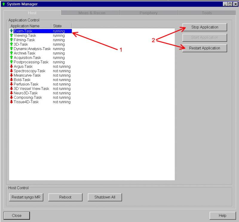
If this doesn’t solve the problem, then check the Meas & Recon and Periphery tabs. There may be a hardware problem (especially if you have a yellow or red icon at the bottom of the screen) and these are quicker to fix.
If the problem is in the Image Reconstruction system, you can choose the Meas & Recon tab, and restart the image calculation software. Choose MrIrisContainer@mars, and then click Restart at right (time to complete – about 30 seconds). Note: This is also a good step to do routinely before your session begins, especially if you’re using cutting-edge sequences.
Also note, the MrIrisContainer has been known to spontaneously re-start, especially when running scans with computationally-intensive reconstructions, so if your scan suddenly wont run in mid-session, look here. The re-start may already be underway – in which case just wait 10-20 more seconds.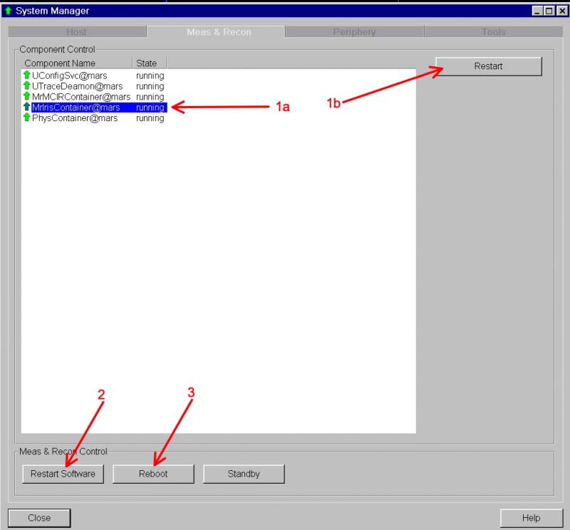
If this doesn’t solve the problem, check the Periphery tab: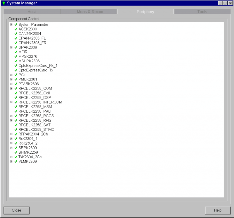
This tab lists all the hardware components of the MR Scanner itself. The list should have all green checks, like in the figure above. If there are red X’s, however, there’s a hardware error, and the hardware system needs to be restarted or power-cycled. Go back to the Meas & Recon tab (above) and either:
2. Restart the operating system of the MR scanner by clicking the “Restart Software” button (Time to complete about 3 min).
3. Reboot the MR scanner hardware by clicking “Reboot”. (Time to complete about 5 min).
After this procedure, check the Periphery tab – everything should have a green check, and the yellow or red lines in the icons at the bottom of the screen should be gone.
If the scanner is still not behaving, then return to the Host tab. There are three “big-stick” options to choose from here: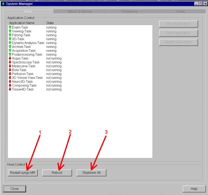
1. Restart the Siemens Syngo program. Click “Restart syngo MR” (Time to complete about 6-8 min).
2. Reboot the Host computer. Click the “Reboot” button. (Time to complete about 10-12 min).
3. Restart the entire system. Click the “Shutdown All” to shutdown the entire MR scanner system. Once the screen states it is safe to shutdown you will need to press the blue “system off” button on the Siemens Alarm Box/Quench Button panel. Wait for a couple of minutes and the press the blue “system on” button. (Time to complete about 15 min). 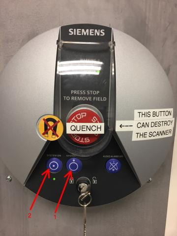
Also note that some error messages are likely to appear during the host computer shutdown and start-up – you can click through these as the appear, and do not need to be reported. Also, on startup, you’ll see some brief flashes of a windows desktop, and there may be a point where the system looks like it has stalled. If you see a completely black screen for more than a few seconds with just the mouse cursor arrow, you need to hit the spacebar to continue.
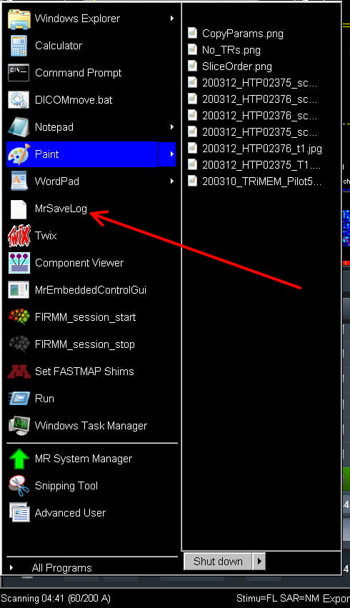
NOTE: Whenever anything has happened that requires a reboot of the host computer or a shutdown of the scanner, please save the system log files so we can work with Siemens to assess what caused the problem. This process creates a very large file of everything the scanner was doing. Siemens accesses this remotely, and can diagnose what caused the problem. This takes about 10-20 minutes, and leaves a bright red text window on the screen until the SaveLog is complete. You can start the SaveLog procedure from the Windows Start Menu – hold Ctl and Esc together, and choose MRSaveLog from the start menu. You’ll then have to enter some basic information like yor name, date/time, and what you were doing when the system crashed, before the procedure runs automatically.